


In today’s dynamic construction landscape, the integration of cutting-edge technologies like Scan to BIM is revolutionizing how MEP Plans (Mechanical, Electrical, and Plumbing) work tracking is optimized. By seamlessly blending laser scanning with Building Information Modeling (BIM), construction teams can achieve unprecedented levels of accuracy, efficiency, and productivity.
Let’s delve into the details of this transformative process. The integration of advanced technologies like Scan to BIM is revolutionizing this process, offering unprecedented levels of accuracy and efficiency. Let’s explore how this innovative approach transforms MEP work tracking.
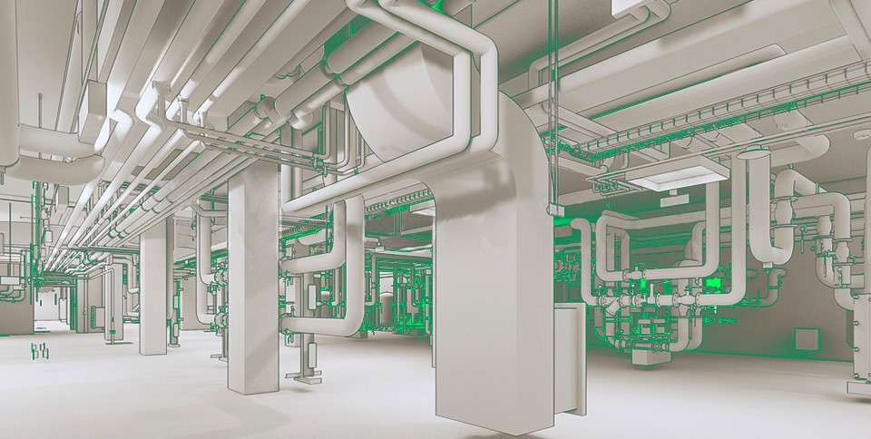
From Laser Scans to BIM:
The journey from laser scans to BIM begins with the collection of highly detailed point cloud data using advanced laser scanning technology.
These scans capture the precise geometry and spatial characteristics of existing structures, including MEP components such as ductwork, piping, and electrical conduits. This rich data serves as the foundation for creating comprehensive BIM models that accurately represent the as-built conditions of the facility.
Scan to BIM Process for Optimizing Work Tracking of MEP Components:
1. Automated 3D Object Recognition Procedure:
In the first phase of the Scan to BIM process, advanced algorithms are employed to automatically recognize and classify MEP components within the point cloud data. This automated 3D object recognition procedure identifies elements such as ducts, pipes, valves, electrical fixtures, and equipment with remarkable precision.
By leveraging machine learning and artificial intelligence techniques, the software swiftly identifies and extracts relevant MEP features, laying the groundwork for subsequent analysis and modeling.
2. Automated Scan-to-BIM Procedure (Deviation Analysis):
Once the MEP components are identified, the automated Scan-to-BIM procedure begins. This phase involves aligning the extracted MEP features with the corresponding elements in the BIM environment.
By comparing the point cloud data to the existing BIM model, the software identifies any deviations or discrepancies between the digital representation and the physical reality. This deviation analysis enables construction teams to pinpoint areas where the model may require adjustments to accurately reflect the actual conditions on-site.
3. Semi-Automated BIM Model Rectification Procedure (Deviation Correction):
Armed with insights from the deviation analysis, the Scan to BIM process enters the rectification phase. Here, skilled BIM technicians utilize semi-automated tools and workflows to rectify any detected deviations in the BIM model. This may involve adjusting the placement, orientation, or dimensions of MEP components to reconcile discrepancies with the point cloud data.
By iteratively refining the BIM model based on real-world measurements, construction teams ensure that the digital representation aligns precisely with the physical environment, laying the groundwork for accurate work tracking and coordination.
Conclusion:
In conclusion, the optimization of MEP work tracking with Scan to BIM represents a paradigm shift in the construction industry. By harnessing the power of laser scanning and BIM technology, construction teams can streamline the process of capturing, analyzing, and modeling MEP components with unparalleled accuracy and efficiency.
This transformative approach not only enhances work tracking and coordination but also lays the foundation for informed decision-making, cost savings, and project success. As construction projects continue to evolve, Scan to BIM remains a cornerstone of innovation and progress in the built environment.

As the editor of the blog, She curate insightful content that sparks curiosity and fosters learning. With a passion for storytelling and a keen eye for detail, she strive to bring diverse perspectives and engaging narratives to readers, ensuring every piece informs, inspires, and enriches.


